Operating principle and procedure
Catalyst filtration is an important aspect of a Hydrogenation system. Omega ‐ Kemix
supplies a cost effective system, which incorporates complete filtration, operational
safety, full backwash, as well as minimal holdup of the reaction mass
At the completion of hydrogenation reaction, balance Hydrogen gas in reactor
headspace is vented, and the Reactor is purged with Nitrogen, to eliminate all traces
of remaining Hydrogen. Subsequently, the Reactor is pressurized to about 1 bar with
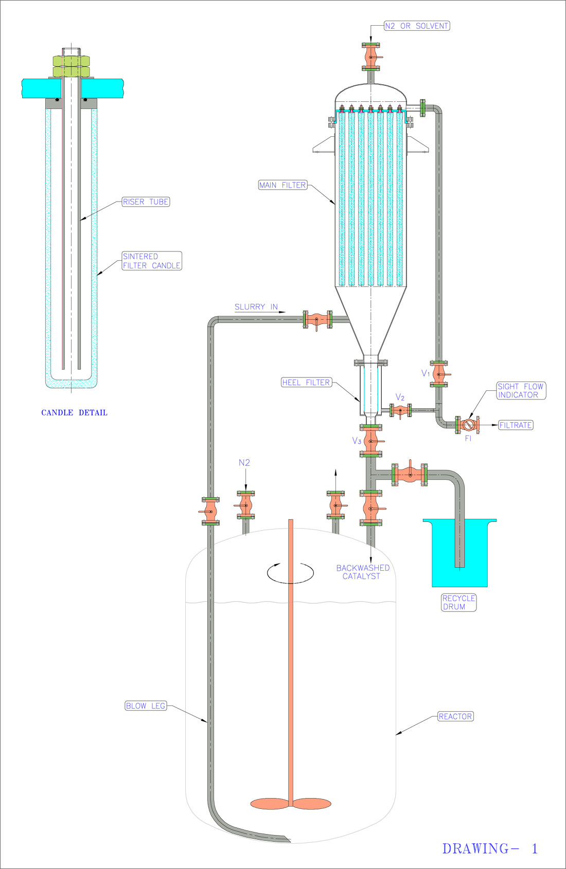
Nitrogen, through Valve V1 Valves V2, V3 and V4 are opened. All othe valves (V5 to
V8) are in closed position. Nitrogen is continuously fed through Valve V1, so that
Reactor pressure is maintained around 1 bar.
Typically, if the catalyst is noble metal on a carrier, e.g., Pd/C, the entire mass is
filtered. In this case, it is advisable to stir the reaction mass at around 50 RPM, and
the dip pipe or blow leg should extend to the lowest possible point in the Reactor.
For heavy metal catalysts like Raney Nickel, the bulk of the catalyst settles within a
very short time, typically 30 minutes after cessation of stirring. In this case, a
common practice is to filter the supernatant liquid (through a dip pipe terminating
just below the lower tan line of the Reactor).
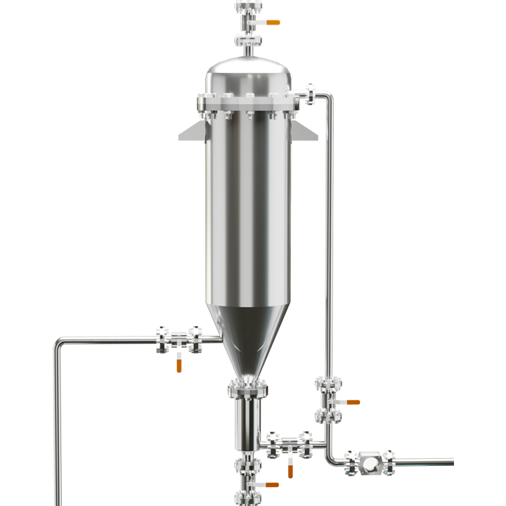
Nitrogen pressure in the Reactor headspace forces the liquid‐catalyst slurry into the
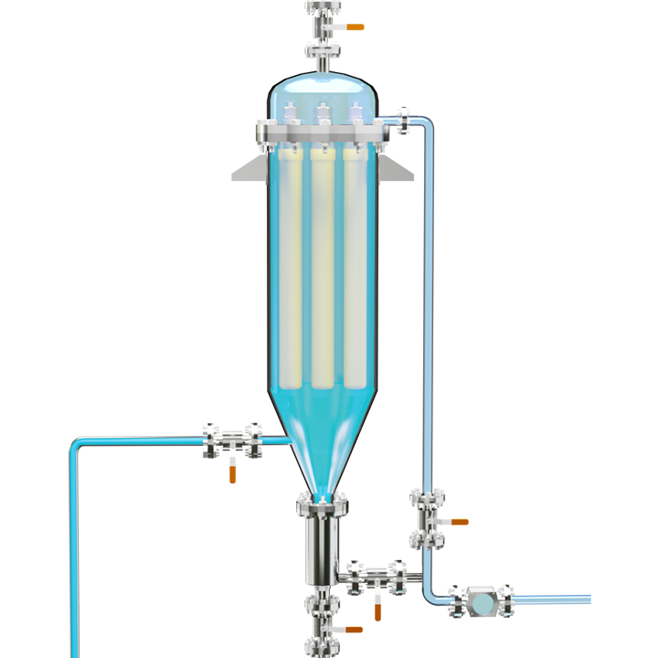
Main Filter through Valve V3. This filter is fitted with sintered SS 316 L candles,
suspended from a tubesheet.
Initially, the Filter body fills up with Liquid‐catalyst slurry. When it is full, filtration
commences. Catalyst cake accumulates outside the candles. Clear filtrate enters the
candles, and flows out through Valve V4. Filtrate flow can be observed through Sight
Flow Indicator (FI).
Once the Reactor contents are entirely displaced by Nitrogen, gas will flow into the
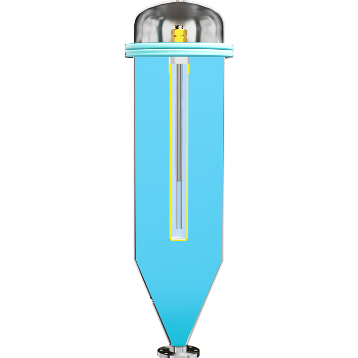
Filter through V3. The Filter Candles are fitted with an inner Siphon Tube. Gas
entering the Filter displaces the slurry, so that clear liquid is siphoned out through
Valve V4 due to action of siphon tubes in the candles. Due to this action, slurr level
in the Filter falls to the lower end of the candles. In effect, the filter cone and lower
parts are full of unfiltered slurry (also known as "Heel"), and candles are coated with
wet cake.
At this point, only gas flows through the Sight Flow Indicator
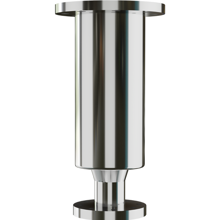
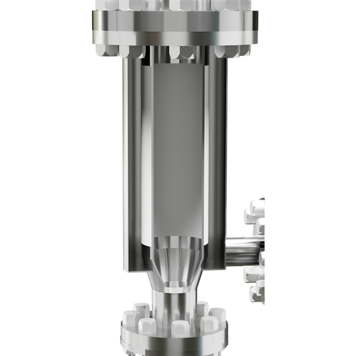
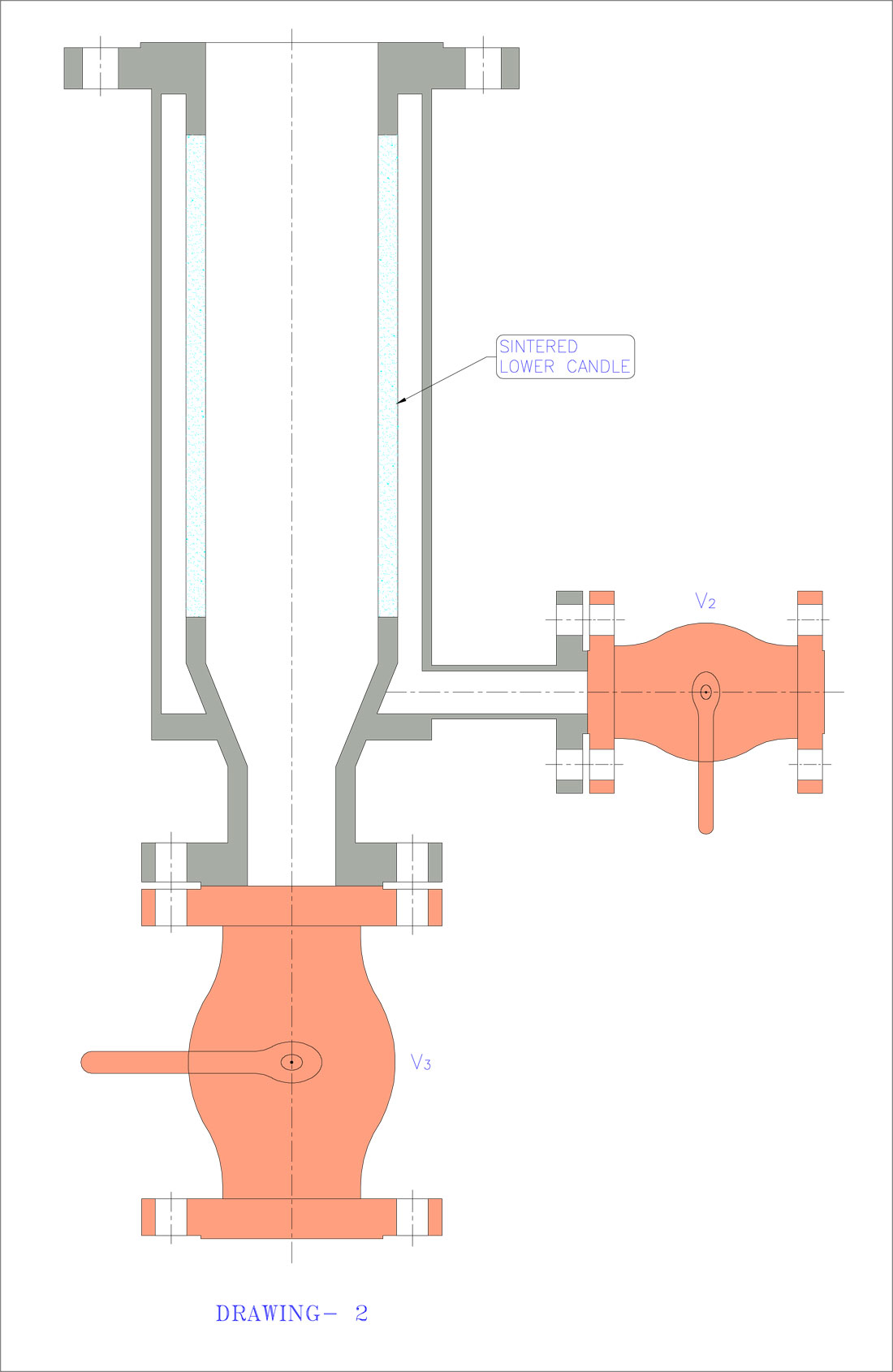
A Zero Holdup Filter is fitted at the lower end of the Main Filter, below the conical
portion. This is a Jacketed Sintered pipe (or Lower Candle), around 125 mm inside
diameter, suitable for inside to outside filtration. Please refer Drawing 2 for details of the Zero Holdup Filter.
When gas flow (i.e., no liquid flow) is observed through the Sight Flow indicator as
described above, Valve V4 is closed, and V9 is opened. Nitrogen gas entering the Filter
cone forces filtrate through the Lower Candle, so that slurry in the Filter Cone and
lower parts is filtered through the Zero Holdup Filter. Heel filtrate is observed flowing
through the Sight Flow Indicator FI.
Once the entire heel slurry is filtered, no further liquid flow is observed through the
Sight Flow Indicator. All the slurry has been filtered. At this stage, outer surfaces of
the upper candles, and inner surface of the lower candle are covered with wet cake.
Valves V9, V3 and V2 and V1 are now closed, and the Reacto vented to atmospheric
pressure, by opening Valve V10. Solvent/feed for the next batch, or Nitrogen at 1 to 5
bar is introduced at Valve V5, located at the top of the Filter. Keeping Valve V10 open,
Valve V8 and then Valve V6 is opened, so that catalyst adhering to candle surfaces
gets back‐flushed into the Reactor.
For best results, Valve V6 should be a Solenoid operated ball valve, so that there is a
pressure pulse while opening this valve. This ensures effective dislodgement of
catalyst cake from the Candles.
This procedure ensures a safe procedure for catalyst filtration from the Autoclave.
There is no spillage of expensive catalyst. The closed circuit operation avoids fire
hazards, as many catalysts are pyrophoric, and can spontaneously ignite when
exposed to air. High efficiency candles result in very low losses, which are often below
measurable limits. The filtration system pays for itself.
After several batch cycles, it may be necessary to remove catalyst from the system,
and send it for disposal or regeneration. In this case, Valve V7 is opened instead of V8,
during back flushing operation, and spent catalyst collected in the Recycle Drum.
 Complete filtration
  Operational safety
  Full backwash
  Minimal holdup of the reaction mass
  Fitted with sintered candles
 Has a special Heel filter
  Provided with a sight flow indicator
  Provided with special valves for effective dislodgement of catalyst cake

